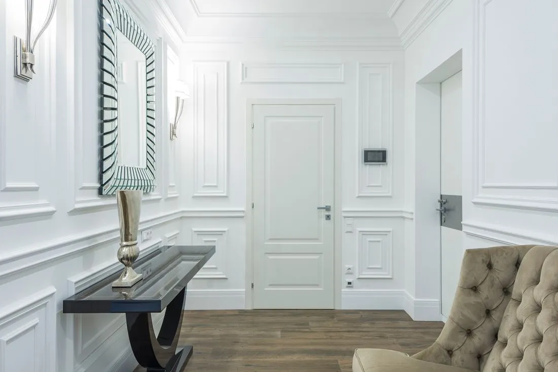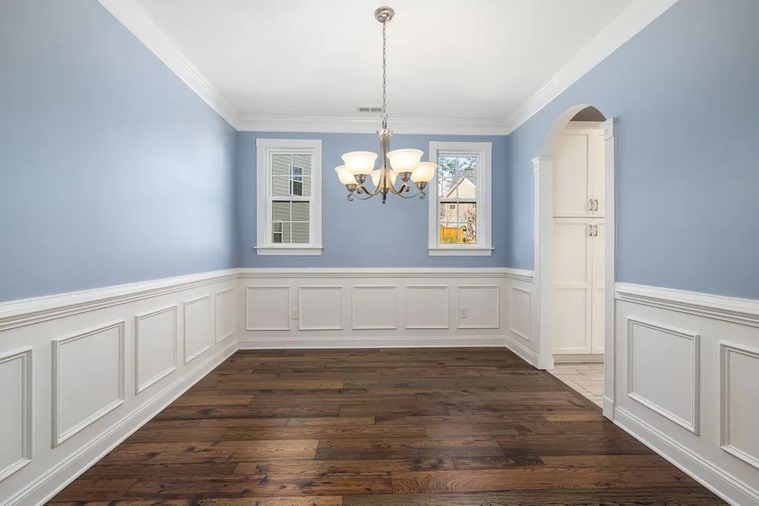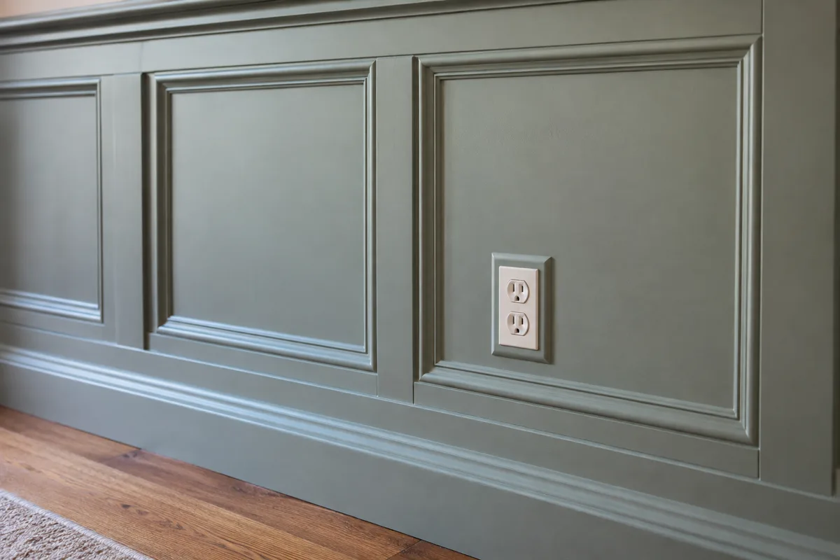
An outlet centered in a proposed molding strip is a layout problem to solve on paper. It is not a reason to notch around the plate after the rest of the wall is finished. Plot electrical devices early, while the panel count and spacing are still easy to change.
Measure the full plate, not just the box opening or visible socket. Also note switches, data points, thermostats, controls, and access covers. Some equipment needs space around it for operation or removal, so its outline on the drawing should include more than the decorative face where applicable.
Make the devices visible in the drawing
A simple wall elevation can use one color for trim and another for devices. Label their positions from a common reference, such as the finished corner and floor. Avoid measuring each outlet from a different nearby object, which makes the plan harder to check.
For a purely illustrative wall, suppose a vertical batten would cross a plate 32 inches from the left corner. Moving only that batten 2 inches may clear the plate, but it creates unequal spaces on both sides. Before accepting that compromise, compare a different starting margin or a different total number of bays. A small change across the whole layout can be less noticeable than one locally bent rhythm.
With picture-frame molding, the plate may sit within an open panel field. That can be preferable to squeezing it into the gap between frames. Keep enough room around the plate that its outline does not nearly touch the molding, producing a cramped double border.
Separate decorative work from electrical work
Adding a backing sheet changes the wall face. The relationship between the electrical box, device, and finished surface then needs to be assessed by a qualified electrician under the applicable requirements. Do not conceal a recessed box, improvise extensions, or cover access with decorative trim.
If relocation is being considered, arrange it before the panel dimensions and finishing sequence are finalized. There may be wiring, framing, or other constraints that make the imagined new position unsuitable. A drawing that assumes every outlet can move is not yet a buildable layout.
The same caution applies to drilling or fastening near wiring. A decorative plan does not reveal concealed services. Establish a safe installation approach with the people doing the work rather than assuming that an unoccupied wall area is clear behind the surface.
Check the finished appearance
Place a spare plate or paper outline within the taped layout. Look at it from the entrance and from the furniture positions where the wall will be seen. An outlet does not need to disappear to look orderly; it needs a reasonable place in the composition.
Avoid painting over devices or making custom plate alterations to blend them into the paneling. Use appropriate finished accessories as intended and retain access for maintenance.
The installation drawing should show the agreed device locations, the final panel lines, and any electrician's work that must happen first. That keeps a well-balanced sketch from reverting to improvised notches when the trim arrives.
A good panel layout accommodates the room's working parts. It does not pretend that the wall is an empty decorative surface and leave the functional conflicts for the last day.