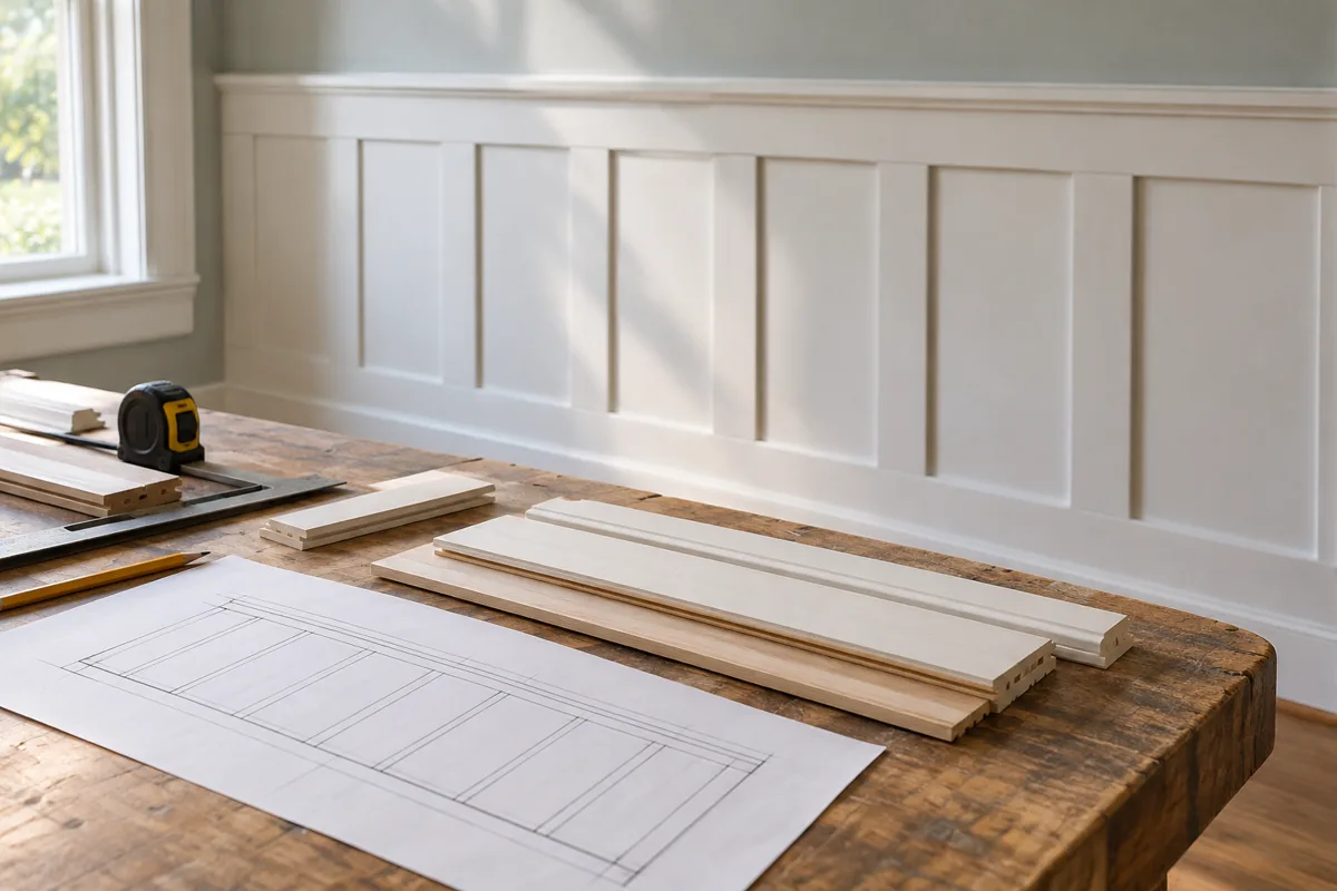
A wall elevation explains the design. A cut plan explains the pieces needed to build it. Moving from one to the other requires more than adding all the line lengths, because joints, saw kerfs, stock sizes, and defects affect how much usable material each board provides.
Use the approved layout, not an early sketch. Check the real wall measurements and the actual molding width first. If a profile substitution changes the width, the visible panel openings and some part dimensions may change too.
Define the measurement convention
For a mitered rectangular frame, specify whether the dimensions are measured between the outside long points, inside short points, or another clearly identified reference. Do not mix those conventions in one list. The installer needs to know exactly which part of the cut the number describes.
Label each frame on the elevation, then list its four sides. A simple naming system such as A-top, A-bottom, A-left, and A-right makes it easier to keep a slightly different panel from being assembled with the wrong pieces.
For square-jointed battens and rails, identify which parts run through and which stop between them. If a vertical strip fits between a top rail and a bottom rail, its length is not the total wall-treatment height. Draw the joint rather than relying on memory.
A small frame example
Suppose four identical frames each have outside dimensions of 24 by 36 inches. In a simplified long-point schedule, that gives eight 24-inch pieces and eight 36-inch pieces. Their combined measured length is 480 inches, or 40 feet.
Buying exactly 40 feet would leave no allowance for the saw cuts, trimming stock ends, defects, or mistakes. It may also be impossible to arrange those parts efficiently within the lengths the supplier sells.
Imagine that 12-foot lengths are available. One provisional arrangement places two 36-inch and two 24-inch parts on each length. Those measured parts total 120 inches, leaving space within the 144-inch board for cuts and trimming. Four such stock lengths would provide the sixteen listed parts, subject to the real cutting method, profile direction, usable ends, and defects.
That is an illustrative allocation, not a universal order recommendation or a claim of maximum efficiency. A different stock length, a directional profile, or a damaged section can change the arrangement. Have the person making the cuts review it before purchasing.
Account for the cuts and the material
A saw removes material at each cut. The blade's kerf, the angle of the cut, and the way adjacent miters are arranged affect the usable length. Do not assume two nominal pieces exactly filling a board leave room for the blade.
Inspect stock for bow, damage, knots, finish defects, or other unusable sections before assigning critical long pieces. A visible stained frame may also require grain and color selection that a painted frame does not.
Long uninterrupted parts usually deserve first attention because they have fewer possible substitutes. Short pieces can often use suitable remnants, but do not plan around scraps that have not yet been produced and checked.
Include separate quantities for caps, base pieces, returns, and any corner components. These are easy to overlook when the main grid dominates the drawing. Keep them distinct from the primary frame molding so a total linear-foot figure does not imply they are interchangeable.
Make the list usable at the bench
Give each part a label, quantity, finished reference length, joint type, and any special note about direction or visible face. A rough cutting allowance can be recorded separately where the installer wants it; do not quietly add it to a dimension labeled as finished.
Check the list against the elevation one last time. Count the frames, count their sides, and confirm that intentional size differences remain intact. A spreadsheet can add lengths accurately while still omitting an entire panel.
Keep the approved sample nearby during cutting. It settles questions about profile orientation more quickly than a paragraph of instructions. Once the pieces are labeled, the wall can be assembled from a clear plan rather than a growing pile of nearly identical lengths.